


Why Choose Our Pure Copper Foil?
- A pure copper foil manufacturing facility with 10+ years of experience, serving hundreds of clients.
- A 30+ material quality control inspection process to achieve high standards and the same quality across batches.
- Free samples and rapid prototyping customisation available
- Compliant with REACH, RoHS 2.0 + HF + PFOS, CMRT CA Prop 65 (US only), UL94, and other regulations
- One-stop services including product selection, customised design, die-cutting, reliability testing, and pre-assembly
Your Reliable Pure Copper Foil Supplier
Benefiting from the exceptionally high conductivity and lower resistance of pure copper foil, it delivers superior and more stable EMI shielding performance. You may use it in high-frequency electronic applications to achieve more reliable products and longer service life. Furthermore, its thickness, dimensions, shape, surface finish and other characteristics can be customised to suit your specific application requirements.
As a trusted Chinese pure copper foil manufacturer, GALLOP INNOTEK provides high-quality electrolytic pure copper foil and rolled pure copper foil. Our in-house laboratory and advanced testing equipment achieve the consistent reliability of our pure copper foil. We also offer a one-stop service from specification selection to pre-assembly, minimising delivery lead times.
Features of Pure Copper Foil

Copper purity up to 99.99% for applications with defined conductivity and material-grade requirements.

Select from 5–200 μm options to balance space constraints, mechanical requirements, and electrical performance.

Compare electrolytic and rolled-annealed foil based on ductility, surface profile, and downstream processing needs.

Request slitting, die cutting, stamping, or lamination according to approved drawings and tolerances.
Flexible Processing and Custom Fabrication
Copper foil can be processed through slitting, die cutting, stamping, and lamination, depending on its thickness, material condition, and application requirements. For parts involving tight bends or complex shapes, confirm the minimum bend radius and forming tolerances through sample testing. GALLOP INNOTEK offers customized foil dimensions and fabrication options to support application-specific designs.


Designed for EMI Applications
GALLOP INNOTEK offers customisable options in multiple thicknesses, dimensions and shapes to facilitate subsequent processing and handling. You may also select varied surface treatments, such as differing degrees of roughness, to achieve diverse bonding applications. Furthermore, pure copper foil can be processed into strip materials, die-cut components and pre-formed coil materials for streamlined subsequent fabrication. We support rapid prototyping and selection guidance to prevent delays and increased costs arising from modifications.
Quality Inspection and Batch Consistency
GALLOP INNOTEK provides copper foil for different application and processing requirements. Before production, confirm the required material grade, thickness tolerance, surface condition, and mechanical properties. Inspection items and acceptance criteria can be defined according to your specifications to support incoming quality checks and batch-to-batch consistency.

Applications of Pure Copper Foil

Pure copper foil can be processed into high-performance EMI shielding materials for use as a shielding layer in electronic equipment, cables, and similar applications.

Copper foil for flexible circuits should be selected according to bending requirements, thickness, material condition, and circuit design. Confirm the required bend radius and flexing cycles for your application.

Copper foil is used in battery current collectors, power electronics, and other electrical assemblies. The required thickness, conductivity, mechanical properties, and surface condition depend on the application and manufacturing process.

Used in automotive, industrial control systems, aerospace and other applications to maintain electrical reliability and control electromagnetic interference.
Successful Project Examples
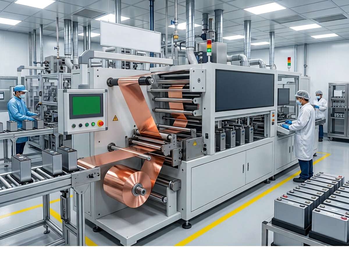
We supplied 99.98% pure, high-purity HTE electrolytic copper foil with surface roughening and anti-oxidation passivation treatments to meet the requirements of the customer’s continuous FR-4 lamination line. The customer had previously experienced peel strength fluctuations of ±8%, with a product yield of only 91%. After switching to our copper foil, peel strength variation narrowed to ±2% and yield increased to 97.2%. With stable monthly deliveries of 32 metric tons, the customer reduced raw material rework costs by 18%, passed the Korean customer’s incoming quality inspection (IQC) audit, and secured a two-year supply agreement.
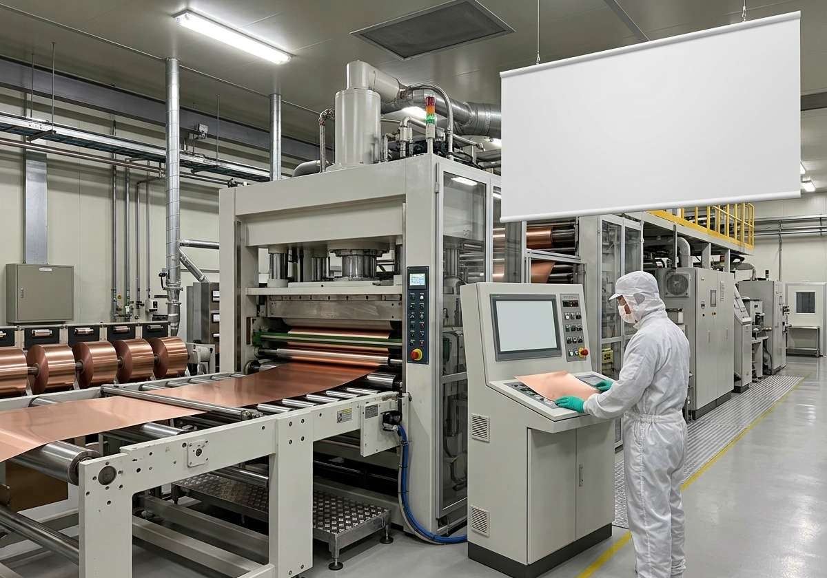
We supplied 6 μm ultra-thin, high-purity lithium battery copper foil with a high-tensile-strength, high-elongation formulation to support the customer’s prismatic energy storage battery production line. The customer’s previous ultra-thin copper foil was prone to web breaks, resulting in an electrode scrap rate of 6.3% and limiting production expansion. After adopting our copper foil, the web break rate dropped to 1.1%, while copper material consumption per GWh of battery production decreased by 7%. The first 45-ton shipment was delivered successfully, and the battery cycle-life validation period was shortened by 40%, supporting the customer’s energy storage expansion plans in the local market.
Specification
- Technical Specifications of Pure Copper Foil
| Parameter | Specifications | What to Confirm Before Ordering |
| Copper Purity | Up to 99.99% Cu | Required purity and material grade |
| Foil Thickness | 5–200 μm | Target thickness and thickness tolerance |
| Copper Foil Type | Electrolytic (ED) / Rolled (RA) | Required ductility, surface profile, and application |
| Width & Dimensions | Customizable | Required width, length, and dimensional tolerances |
| Supply Form | Foil strips, die-cut parts, pre-formed coil materials | Roll or component format required for production |
| Surface Finish | Customizable surface roughness and treatment | Bonding requirements, substrate, and target surface roughness |
| Electrical Conductivity | Approaching 100% IACS | Required conductivity and test method |
| Mechanical Properties | Adjustable to application requirements | Tensile strength, elongation, and material temper |
| Processing Options | Slitting, die cutting, stamping, lamination, and forming | Drawings, part dimensions, edge quality, and forming requirements |
| Quality Inspection | 30+ material quality control inspection processes | Required inspection items and acceptance criteria |
| Samples & Prototyping | Free samples and rapid prototyping available | Sample dimensions, testing requirements, and project schedule |
Pure copper foil with higher copper content can offer lower electrical resistivity and higher conductivity, depending on the material grade and condition. However, EMI shielding effectiveness also depends on foil thickness, operating frequency, shielding structure, and electrical continuity. Compare the actual material specifications and test data before selecting a grade for your application.
Higher copper purity can support higher electrical conductivity and lower resistivity, but it does not automatically guarantee better EMI shielding effectiveness. The right grade depends on your target frequency range, foil thickness, shielding structure, and electrical connections. Higher-purity grades may also cost more. Compare material specifications and test results against your application requirements before selecting a grade.
Thinner copper foil reduces material weight and may suit compact designs, but its electrical resistance per square area is generally higher than that of thicker foil. Thicker foil can reduce electrical resistance and may improve shielding performance in some designs. Actual EMI shielding effectiveness and heat dissipation depend on the operating frequency, shielding geometry, thermal path, and assembly conditions. Select the thickness based on your electrical, thermal, mechanical, and dimensional requirements.
Electrolytic copper foil (ED) is formed through electrodeposition, while rolled annealed copper foil (RA) is produced through rolling and annealing. Their surface profiles, ductility, and mechanical properties vary by product grade, thickness, and surface treatment. RA foil is often considered for applications requiring greater flexibility, while ED foil is widely used in electronic materials. Compare the technical data for the specific grades before making a selection.
High-purity copper foil may contain up to 99.99% copper, depending on the specified grade. The remaining composition, including any trace impurities or intentionally added elements, should be verified against the material specification or chemical analysis report.
Pure copper foil can reflect interfering electromagnetic waves, preventing them from entering equipment. It can also utilise its high conductivity through grounding design to divert interference currents into the earth connection.
Surface roughness affects how well pure copper foil bonds with coatings, adhesives, and other materials. It can also affect signal loss in high-frequency circuits. If you use copper foil for battery anode current collectors, you need to balance surface adhesion with uniform coating. For high-frequency PCBs, focus on the roughness of the contact surface to reduce extra signal loss. When choosing copper foil, check the roughness range, test method, and surface type for your application. A smoother surface is not always the best choice.
Tensile strength shows how much pulling force copper foil can withstand before breaking. Elongation shows how much it can stretch before breaking. If your process involves rolling, bending, or continuous production, you need a good balance between strength and flexibility. This helps reduce cracking, wrinkles, and breaks during processing. For battery anode current collectors, you should also consider coating, rolling, and cell assembly requirements. When requesting a quote, share your target thickness, processing methods, and required mechanical properties. Make sure the test conditions are clear, as results can vary by thickness, material condition, and test method.
Pinholes can affect performance depending on their size, number, and location, as well as your application. For battery anode current collectors, they may affect coating quality and local electrical performance. For PCBs and precision electronic materials, pinholes can cause circuit defects or reduce product reliability. If your application requires defect-free foil, define the acceptable pinhole size and number, inspection method, and acceptance criteria before placing an order. You should also ask your supplier about surface inspection and quality records. A smooth-looking surface alone does not guarantee that the foil meets your requirements.
Yes. Pure copper foil is widely used as a current collector for lithium-ion battery anodes. It supports the anode active material and conducts electrical current. However, not every type of copper foil suits your battery design. You need to consider thickness, tensile strength, elongation, surface roughness, surface treatment, and pinhole control. These properties must also match your coating, rolling, and cell assembly processes. If you are developing a battery or sourcing copper foil for mass production, share your battery type, target thickness, mechanical properties, and surface requirements with your supplier. This helps you confirm whether the foil meets your needs and delivers consistent quality across batches.
Yes, but you need to choose the right copper foil based on your operating frequency, signal loss limits, and PCB design. At high frequencies, the skin effect causes current to flow mainly near the conductor’s surface. Surface roughness can increase signal loss, while the bond between the copper foil and substrate must remain strong enough for lamination and further processing. If you use copper foil for high-frequency PCBs, check its surface roughness, thickness tolerance, surface treatment, and compatibility with your chosen substrate. You should also evaluate signal loss at your target frequency. Standard pure copper foil may not meet the requirements of every high-frequency application.
Pure copper foil can oxidize or change color during storage and shipping due to moisture, oxygen, contaminants, and direct contact with hands. These changes may affect surface quality and make further processing more difficult. If you need to store copper foil for a long time or ship it overseas, keep it in a clean, dry environment and use suitable moisture-resistant, sealed packaging. Avoid contact with water, corrosive substances, and contaminants. You should also confirm whether an anti-oxidation treatment is needed for your application. Before ordering, discuss packaging, storage conditions, shelf life, and handling after opening with your supplier. For battery and electronic applications, make sure the treatment does not affect conductivity, solderability, or bonding with other materials.
What is Pure Copper Foil?
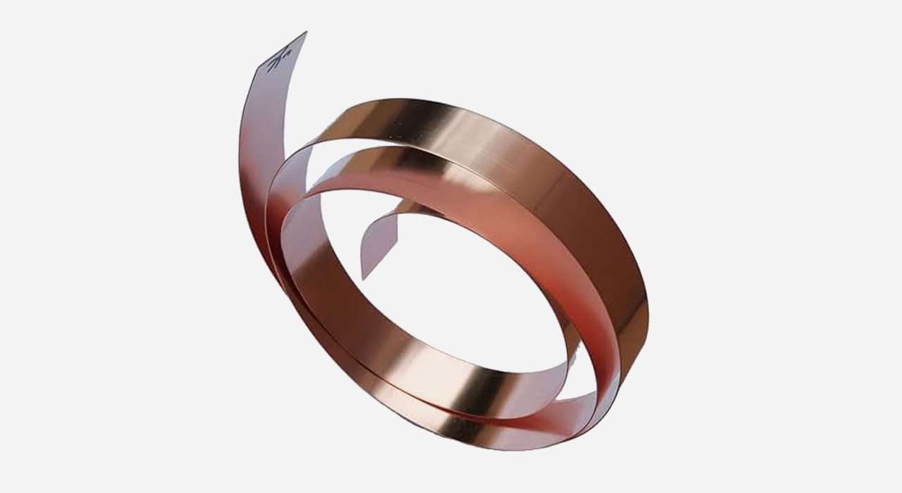
Pure copper foil is a thin copper material used in electronic, electrical, and thermal applications. High-purity grades can contain up to 99.99% copper, depending on the material specification. Its electrical and thermal properties depend on copper purity, foil thickness, material condition, and manufacturing process. Common types include electrolytic copper foil (ED) and rolled annealed copper foil (RA), each suited to different processing and application requirements.
Types of Pure Copper Foil
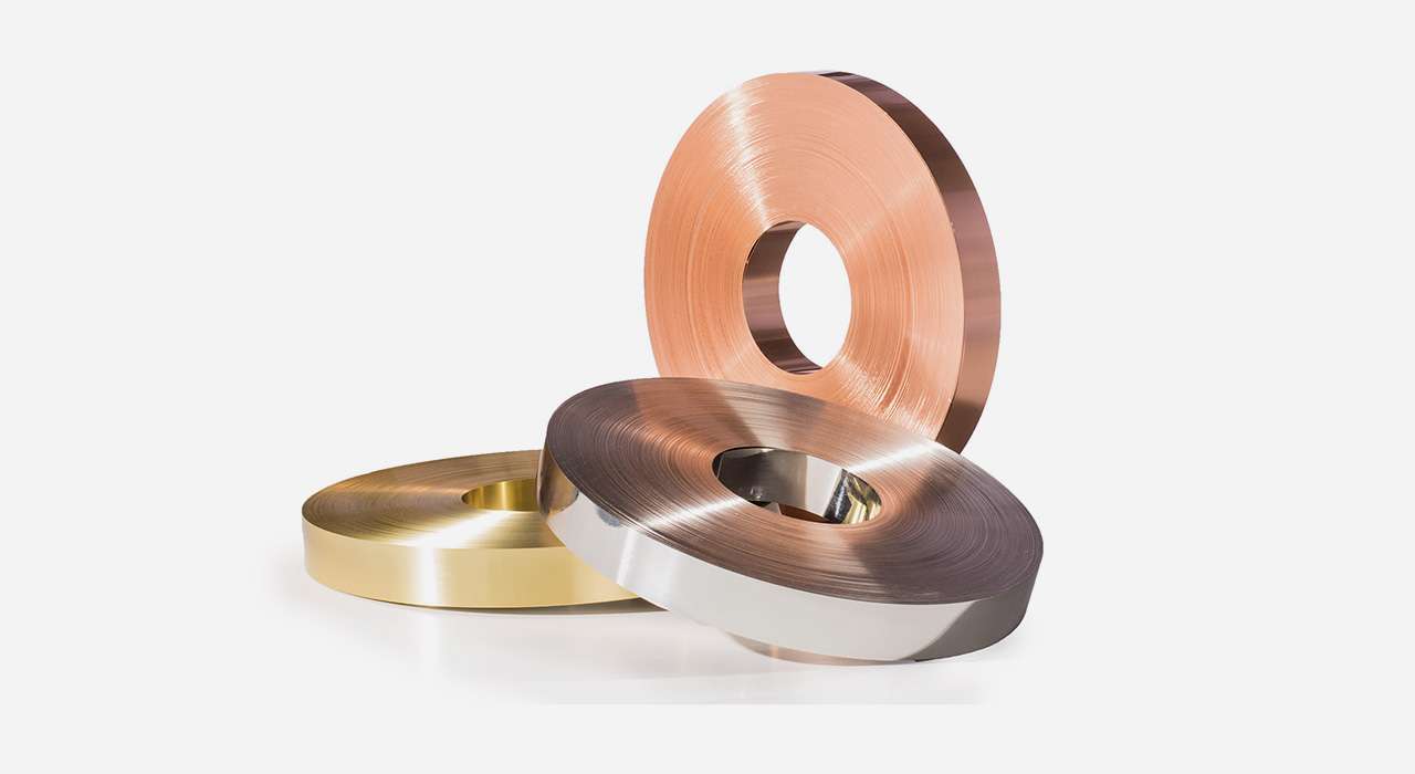
Electrolytic Pure Copper Foil
Electrolytic pure copper foil is produced by electroplating high-purity copper. As this process is more straightforward, it has a lower initial cost. It is thicker and rougher, making it suitable for rigid PCBs and providing better adhesion to substrates. However, the rough surface also results in greater signal transmission loss. Nevertheless, it remains highly cost-effective.
Rolled Pure Copper Foil
Rolled pure copper foil is produced through physical processing such as rolling and high-temperature annealing. Following rolling, the pure copper foil becomes thinner and smoother, requiring roughening treatment to achieve greater bonding capability. Its processing is more complex and necessitates more expensive processing equipment. Consequently, you may incur higher costs. However, it possesses superior ductility compared to electrolytic pure copper foil.
How to Choose the Right Pure Copper Foil?
Select Based on Electrical Requirements
For current-carrying applications, evaluate the foil thickness, conductor width, current load, allowable temperature rise, and operating environment. For EMI shielding, also consider the target frequency range, required shielding effectiveness, electrical continuity, and grounding design. Lower electrical resistance alone does not guarantee better shielding performance, so validate the complete design against your application requirements.
Consider the Operating Environment
Different applications impose varying requirements on pure copper foil. For instance, in EMI shielding and ground connections, low resistance should be considered. For applications requiring auxiliary heat dissipation, you need to know the thickness of the copper foil. For flexible electronics, however, one should select pure copper foil with superior resistance to bending.
Select the Thickness of Pure Copper Foil
Copper foil thickness affects electrical resistance, current-carrying capacity, flexibility, and dimensional stability. Thinner foil may be easier to fit into compact or flexible assemblies, while thicker foil generally offers lower electrical resistance for the same conductor width and length. Bending performance also depends on material type, temper, bend radius, and forming conditions. For EMI shielding, evaluate thickness together with frequency, coverage, seams, and grounding. Confirm the required properties with the supplier before production.
Pure Copper Foil for EMI Shielding
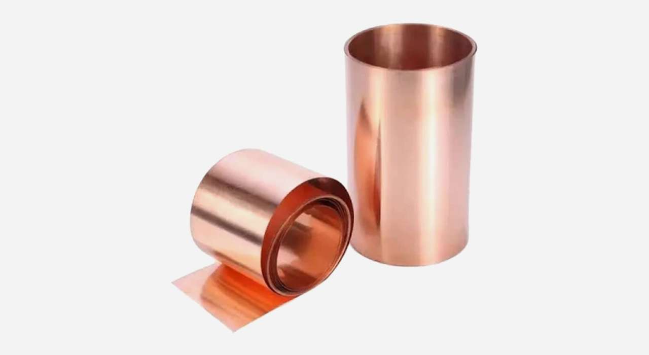
How Does Pure Copper Foil Block EMI?
Pure copper foil helps reduce electromagnetic interference (EMI) by reflecting electromagnetic energy and absorbing part of it. You can use it as a conductive layer to protect circuit boards, electronic components, and signal lines from unwanted interference. However, the foil alone does not guarantee effective shielding. You also need to control coverage, seams, openings, and electrical connections to prevent interference from entering through gaps in the structure.
How Does Frequency Affect Copper Foil Shielding?
The shielding effect of copper foil depends on the frequency of the interference and the design of the shielding structure. At high frequencies, gaps, seams, and cable openings can become major paths for electromagnetic leakage. At low frequencies, especially with magnetic fields, a thin copper foil layer may provide limited protection. If your equipment operates across multiple frequency ranges, define the target frequency range and required shielding effectiveness first. You can then test the complete shielding assembly under those conditions instead of relying on the copper foil’s conductivity alone.
Why Do Grounding and Electrical Connections Matter?
A copper foil shield needs proper electrical connections to work as intended. If the contact points are loose, painted, contaminated, or poorly connected, interference can pass through the gaps in the shielding path. When designing your assembly, define where the foil connects to the ground plane, metal housing, or other conductive parts. If you use adhesive-backed copper foil, check whether the adhesive is electrically conductive. Standard insulating adhesive may hold the foil in place but cannot provide a reliable electrical connection by itself. Confirm the contact method and connection points before assembly to avoid costly rework.
How to Design Copper Foil for EMI Shielding Structures?
Copper foil can be integrated into shielding structures as a standalone conductive layer or combined with insulating films, adhesives, and metal housings. For example, you can laminate the foil onto an insulating film and apply the assembly over a designated area of a circuit board or enclosure. During design, pay attention to edges, joints, openings, and cable entry points. These areas can interrupt the shielding path and allow electromagnetic leakage. If the foil must follow a curved surface or pass through a folded section, account for the forming process and assembly tolerances in advance. This helps maintain continuous shielding coverage in the finished product.
Pure Copper Foil Processing and Fabrication
Cutting Pure Copper Foil to Size
Slitting, die cutting, and precision cutting can turn copper foil into the widths and shapes required for your parts. During production, control the finished width, length, dimensional tolerances, and edge condition. Burrs, curled edges, and uneven cuts can cause alignment problems during assembly. If your parts need to fit circuit boards, insulating films, or other components, confirm the drawing dimensions and tolerance limits before production.
Stamping Pure Copper Foil into Custom Shapes
Stamping and die cutting are useful for producing copper foil parts with repeatable outlines, holes, and openings. These processes work well for shielding pieces, conductive tabs, and other custom components. The die clearance, material thickness, and tool condition all affect the finished result. Poor settings can cause burrs, torn edges, or misplaced holes. If your parts require precise assembly, check the first samples against your drawings before moving to mass production. You should also define acceptable edge quality and hole-position tolerances to reduce fitting problems later.
Bending Pure Copper Foil Without Cracking
Bending allows copper foil to fit around housings, connection points, and other shaped surfaces. The bending radius, foil thickness, and material condition affect the final shape. A bend that is too tight or repeated bending can cause wrinkles, cracks, or local thinning. These defects may also interrupt electrical continuity in conductive parts. If your design includes sharp corners or multiple bends, confirm the required bend radius and test sample parts before production. After bending, inspect the formed areas for cracks, wrinkles, and other defects that could affect assembly or electrical performance.
Laminating Copper Foil with Other Materials
Lamination bonds copper foil to insulating films, plastic substrates, or other materials to create a multilayer structure. During this process, you need to control temperature, pressure, and lamination time according to the materials and adhesive used. Incorrect settings can lead to bubbles, weak bonding, edge lifting, or delamination. Before production, confirm that the foil, adhesive, and substrate are compatible with each other. For parts exposed to temperature changes or long-term use, check the bond strength and edge condition after lamination. This helps prevent the layers from separating during later processing or use.
Forming Copper Foil into Three-Dimensional Shapes
Press forming and other forming methods can shape copper foil to fit curved surfaces, recesses, and other three-dimensional designs. Unlike flat cutting, these processes cause the material to stretch and change shape. Forming depth, tool geometry, and material flexibility all affect the result. Excessive forming can cause wrinkles, cracks, local thinning, or springback that changes the final dimensions. If your parts must fit closely inside an enclosure or around other components, test the forming process with sample parts first. Confirm the final dimensions and surface condition before setting the parameters for mass production.

